Routing in IP networks
Static routing, RIPv2 and BGP across four autonomous systems on FRR routers.
Goal: understand how an IP router works; gain hands-on experience building routing tables and running interior and exterior routing protocols.
This practical work was moved from Cisco Packet Tracer to GNS3. The routers here run FRR: its command line is modelled on Cisco IOS, and the command table lists where it differs.
Background
Routers (hardware or software) choose the best path for an IP packet and send the packet along it. To decide, a router looks at the destination address and picks the path from formal records describing the structure of the internetwork. These records are called routing tables.
A routing table has at least these fields: the destination (an IP network or a host address), the port the packet leaves through towards the destination (named by its IP address or an internal number), the gateway (the IP address the packet goes to after it leaves the port), and the metric (how good the route is).
Every router in the network holds a table that fully describes the structure of the whole network and sometimes contains default routes.
Routing tables are written by hand or built by interior routing protocols that automate the process. RIP2 is one such protocol.
These protocols run inside autonomous systems. An autonomous system (AS) on the Internet is a set of IP networks and routers run by one or more operators with a single routing policy towards the Internet.
Autonomous systems exchange routing information through exterior routing protocols such as BGP. BGP (Border Gateway Protocol) is the main dynamic routing protocol of the Internet. It carries aggregated routes between networks (autonomous systems): in effect, which networks belong to which AS and how the AS connect to each other. The junction between two providers, in particular, is built with BGP.
Main commands
The router console opens straight into its command line. "Same" in the FRR column means the command is written as in Cisco IOS.
| Cisco IOS | FRR | Purpose |
|---|---|---|
enable | same | enter privileged mode |
configure terminal | same | enter configuration mode |
interface <PORT_NAME> | interface eth0 | configure a port |
ip address <IP> <MASK> | ip address <IP>/<PREFIX> | assign an IP address and mask |
copy running-config startup-config | same | save the running configuration |
exit | same | leave a configuration context or configuration mode |
show ip interface | show interface | show IP on the interfaces |
show ip interface brief | show interface brief | brief IP summary of the interfaces |
no shutdown | same | enable an interface (disabled by default) |
ip route <IP> <MASK> <GATEWAY> | same | add a route |
no ip route <IP> <MASK> <GATEWAY> | same | remove a route |
show ip route | same | show the routing table |
no auto-summary | not needed | turn off automatic route summarisation; RIPv2 in FRR never summarises |
router rip | same | enable RIP |
version 2 | same | use RIP version 2 |
network <NETWORK> | network <NETWORK>/<PREFIX> | advertise a network to other routers (RIP) |
network <NETWORK> mask <MASK> | same | the same with an explicit mask (BGP) |
passive-interface <PORT_NAME> | same | do not send the table through an interface |
default-information originate | same | the RIP router advertises itself as the default gateway |
debug ip rip | debug rip events | RIP debug messages; terminal monitor prints them to the console |
hostname <HOSTNAME> | same | set the host name |
ping <IP> | same | check reachability over ICMP; on a router it runs until you stop it with Ctrl+C |
traceroute <IP> | same | trace the route |
router bgp <AS> | same | enable BGP on the edge router with its AS number |
neighbor <IP> remote-as <AS> | same | peer with the edge router at IP that serves the AS |
| — | no bgp ebgp-requires-policy | in router bgp: without it FRR exchanges no routes with peers in other AS (RFC 8212) |
bgp log-neighbor-changes | same | log BGP neighbour state changes |
show ip bgp neighbors | same | peer details |
show ip bgp summary | same | BGP state summary |
The PCs are VPCS:
| Command | Purpose |
|---|---|
ip <IP>/<PREFIX> <GATEWAY> | address, mask and gateway |
save | save the settings |
show ip | show the address and gateway |
ping <IP> | check reachability over ICMP |
trace <IP> | trace the route |
Network
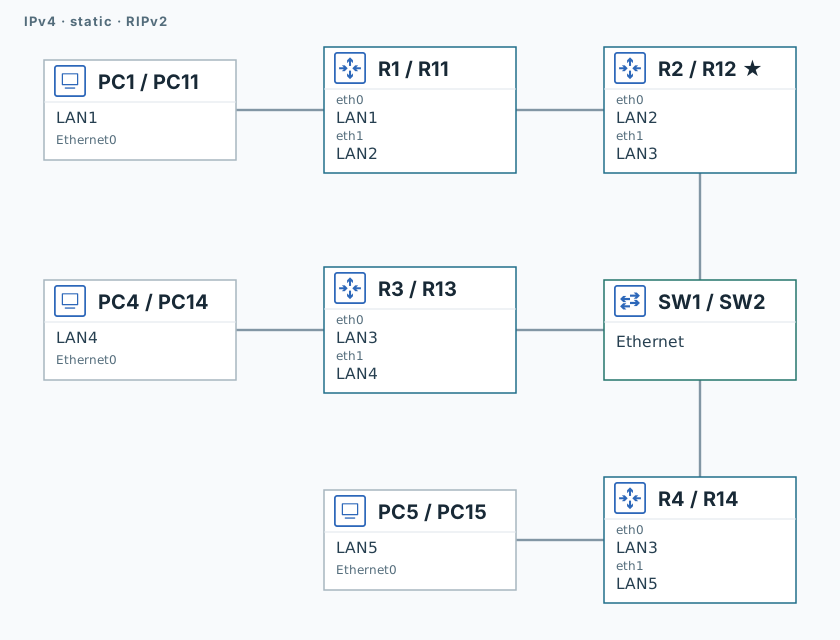
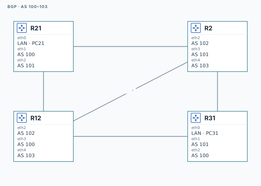
The network is already built: nodes, cables and interfaces are in place. The routers are as if new: no addresses, every interface shut down. You configure everything else.
How to open a console
Save your settings: copy running-config startup-config on a router, save on a PC. They then survive a node restart.
1. Infrastructure
- The network of figure 1 is already built as AS 100. Network 3 (LAN3) is one local network in which routers R2, R3 and R4 connect through switch SW1. Networks 1, 4 and 5 each hold one PC: PC1, PC4, PC5.
- Equipment: switch SW1 (1), routers R1–R4 (4), PCs (3), interfaces and cables as needed.
- Take the subnets for all networks from 192.168.0.0/24.
- Assign addresses to the router interfaces and enable the interfaces. Give each PC an address and a gateway with
ip <IP>/<PREFIX> <GATEWAY>, thensave. - Check that the nearest neighbours in each local network are reachable.
For example, one router interface:
R1
configure terminalinterface eth0 ip address <IP>/<PREFIX> no shutdownexit2. Static routing
- Configure static routing in this network.
- Check that packets pass between all nodes of the model.
- Print and save the routing tables of all routers.
3. Dynamic routing
- A copy of your network is already built: routers R11, R12, R13, R14, switch SW2, PCs PC11 (LAN1), PC14 (LAN4), PC15 (LAN5). The router with the star is R12.
- Take the subnets for all networks from 192.168.1.0/24.
- Check that the nearest neighbours in each local network are reachable.
- Configure RIP2 on all routers so that:
- routes are not summarised;
- tables are sent only through interfaces connected to other routers.
- Turn on debug output to the router consoles.
- Make sure all the information needed has arrived.
- Check that packets pass between all nodes of the model.
- Print and save the routing tables of all routers.
4. Additional networks
- Two additional networks of one router and one PC are already built: R21 with PC21 and R31 with PC31. The PC connects to the router's eth0.
- Address them from 192.168.2.0/24 (R21, PC21) and 192.168.3.0/24 (R31, PC31).
5. Joining the networks
-
The networks you built are autonomous systems. Use these AS numbers:
Network AS Edge router 192.168.0.0/24 100 R2 192.168.1.0/24 101 R12 192.168.2.0/24 102 R21 192.168.3.0/24 103 R31 -
The networks are connected as in figure 2, and the interfaces needed are already added: eth2–eth4 on R2 and R12, eth1–eth2 on R21 and R31. Use separate subnets of 10.0.0.0/16 for the links.
-
Configure the edge routers. For AS 100 and 101 it is the router marked with a star in figure 1. For the other AS it is their only router. Peer with every AS. In FRR, add
no bgp ebgp-requires-policytorouter bgp. -
Watch the routing tables to make sure the routes were updated.
-
Inside AS 100, on the routers that are not edge routers, set the default gateway to the matching internal IP of the edge router. Use the standard address 0.0.0.0 with mask 0.0.0.0.
-
On the edge router of AS 101, use
default-information originate(inrouter rip) to spread the default route. The other routers of the network should pick it up by themselves. -
Trace the route between PCs of all AS. When tracing from AS 100 and AS 101, use one PC from LAN1 and one from LAN5.
-
Cut the link between AS 102 and AS 100. Repeat the trace. Compare the results.
Note. A BGP router announces only the networks it has routes to. In AS 101 all IP networks belong to one large IP network. It makes sense to announce that whole network once rather than each small network separately. To do so, add a route to the whole network on the router, with interface Null0 as the gateway (for example ip route 192.168.0.0 255.255.255.0 Null0).
Cutting a link in GNS3. Shutting an interface down does not reach the far end of the cable, so cut the link at both ends: shutdown on R21 eth1 and on R2 eth2. If you shut only one side, BGP notices the break only when the hold time (180 s) runs out. After comparing, bring the link back up (no shutdown at both ends) and wait for the peering to recover: the check expects peerings with every AS.
Report
Prepare a report as DOC/DOCX or PDF. It contains a title page, the artefacts of the work and the answers to the questions and tasks.
Artefacts:
- The commands configuring the router marked with a star, from parts 2 and 3.
- The BGP commands on these routers from part 5.
- The final routing tables from part 5.
- The peer (neighbor) output from the edge router of AS 100.
show running-config prints a router's current commands.
Questions and tasks:
- Explain the results of part 5, item 7.
- With access to a router console, how can you tell that BGP updates are coming through?
- What differences between configuring and running BGP and RIP did you notice during the work?
Key concepts
- IP network
- Route
- Metric
- Routing table
- Default gateway
- The order of route lookup in a routing table
- RIP, how it spreads routing information
- BGP, how it spreads routing information
- BGP peer
- BGP network announcement
Validation
The five validation steps match parts 1–5. No specific address is checked: only that addresses come from the right network, which protocol a route came from, and whether the PCs can ping each other. In part 5, R12 must announce AS 101 as one network, 192.168.1.0/24, through a route to Null0 (see the note). The link between AS 102 and AS 100 must be up before you check.
Click "Check". Once all steps pass, click "End".